Appendix K
How to make a Bush HandpumpThe Zimbabwe pump (also known as the Bush Pump) is build around a down-hole cylinder containing a piston. It is called a "positive displacement pump" because it displaces an amount of water equal to the distance the piston travels. The amount of water pumped is limited by the piston diameter and length and the number of pump strokes per minute.
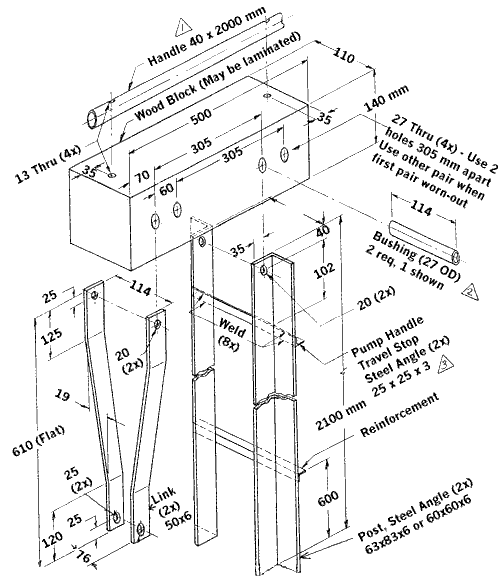
Pump cylinders are connected by pump rods to a lever handle (see Figure 25 and Figure 26). A wooden hand grip can be attached directly to the pump rods if:
|
The rising main is usually made of PVC. Galvanized rod is commonly used for the pump rod. Reinforced steel can be used but it is likely to rust.
The Zimbabwe pump stand, handle and bearing usually are the first parts to wear out and are also relatively easy to build. For this reason, they should be considered the principle elements for local manufacture:
- The main pump bearing is made of wood. It can be one solid wood block or can be made from three laminated pieces. The wood bearing works best if it is first soaked with oil
- The handle may be made of wood, but a steel pipe is usually used for strength. Attach the handle to the wood block with 12 or 13 mm diameter bolts, 200 mm long (see Item #1 on Figure 25). Use large-area washer (45 OD x 13 ID) and lock washer (13 ID) between each nut and block.
- The bushings should be 3-4 mm longer than the width of the block of wood (see Item #2 on Figure 25). This will allow bolts (20 mm dia, 150-165 mm long) to be completely tightened without the block being stuck tight between the steel pump supports. If the bushings are the correct length, the block will freely rotate up and down without significant sideways movement. Before assembling, soak the holes in the wood liberally with oil. Used engine oil may even be used. Use 20 mm ID lock-washers behind each nut
- The aft handle bolt should hit the "pump handle travel stop" angle iron bar when the end of the handle is all the way down (see Figure 25).
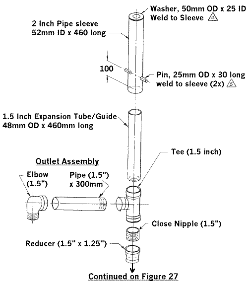
- Use one or two large-area washers (#1,2 or 3 with 1/2 inch ID) on top of the 25 mm ID washer which is welded to the top of the pump sleeve (see Item #4 on Figure 26). Alternatively, instead of using a 50 mm OD x 25 ID washer, use steel plate (3 mm thick or more) cut to fit with a center hole the diameter of the pump rod. If the end of the 5 cm (2 in) pipe is threaded, screw-on a 5 cm (2 in) cap with a hole (diameter equal to the pump rod diameter) drilled in the center. When the pump rod is inserted through the top of the pump sleeve, secure it in place using two nuts, tightened against each other.
- It is really important to line-up the two pins which are to be welded onto the pump sleeve (see Item #5 on Figure 26). This can be done by drilling a 2 cm (1 in) hole right through both walls of the pump sleeve, inserting a pin into the hole until it is flush with the inside of the pipe wall and then welding. An even better way to align the two pins is the make a "jig" using the two flat-bar links shown on figure 25. Attach the links to the wood bearing block and then lay the links on their long edge on a flat surface straddling the 5 cm (2 in) pipe. Make sure the pipe is parallel to the two links and raise the links 6 mm (1/4 in) so that the pins will be centered on the pipe wall. Insert the steel pins in the 2 cm (1 in) holes at the end of the links and position the pipe so that the pins will be located at the specified distance from the bottom end of the pipe. Tag-weld the pins, remove the links and finish welding. After the pins are attached to the pump sleeve, install 2 steel washers (50 mm OD x 25 mm ID x 3 mm thick), on each pin - one on each side of the flat bars which link the wooden bearing block to the pump sleeve (total of 4 washers required).
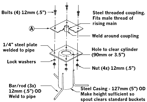
- The outlet assembly should be supported on a reinforced casing base (Figure 27). Install the reinforced casing base as follows:
- Place the steel base over the PVC casing before pouring the concrete pad. Allow concrete to dry 2-3 days.
- After installing the cylinder and rising main, attach the rising main to the welded coupling in the casing base plate, position the plate on the base and secure with 4 bolts (see item "A" on Figure 27)
- Install outlet assembly (figure 26) to welded coupling (item A).
Figure 25: Bush Pump Fabrication

Figure 26: Bush Pump Outlet Assembly Detail

Figure 27: Bush pump casing reinforcement

| The most difficult part to get for making a Bush or Zimbabwe pump is often the large bolts (20 mm diameter, 150-165 mm long) used to connect the wood block bearing to the angle iron pump post (Figure 25). The most difficult part to make is welding the pins onto the pump sleeve (Item #5 on Figure 26). Depending on the availability of material, the most expensive parts to make are often the pump post made from angle iron (Figure 25) or the casing reinforcement base (Figure 27) |
![]()